Mobile/Whatsapp
+86-15922982738
- All
- Product Name
- Product Keyword
- Product Model
- Product Summary
- Product Description
- Multi Field Search
 English


 |


| Quantity: | |
|---|---|


ISO 1182 EN 13501 A1 level Non-flammability test furnace
Product Introduce
The ISO 1182 non-combustibility test furnace is a specialized apparatus designed to evaluate the non-combustible properties of building materials and products, adhering to ISO 1182:2020 and equivalent international standards such as EN ISO 1182, BS EN ISO 1182, ASTM E136, and IMO FTP Code Part 1. Operating at a precise 750°C, it tests cylindrical samples (45 mm diameter, 50 mm height) to measure temperature rise (≤ 50°C for furnace, surface, and center), sustained flaming (none for A1, ≤ 20 seconds for A2), and mass loss (≤ 50% for A1), ensuring compliance with fire safety classifications like Euroclass A1 and A2. Widely used in construction, rail, marine, and aviation industries, this furnace features advanced dual thermocouples, automated temperature control, and real-time data acquisition, making it essential for certifying materials in high-fire-risk applications.
Standard
1. International Standard
ISO 1182:2020
Title: Reaction to fire tests for products — Non-combustibility test
Description: Specifies the test method for determining the non-combustibility of the main components of homogeneous products and non-homogeneous products under specific conditions.
Remarks: The latest version, superseding ISO 1182:2010 and earlier versions (1983, 1990), adds the requirement of dual thermocouples (furnace wall temperature monitoring)
2. British Standard
BS 476-4:1970+A1:2014
Title: Fire tests on building materials and structures — Part 4: Non-combustibility test for materials
Description: British domestic standard, similar to ISO 1182, the test method is based on 750°C furnace temperature, determines the non-combustibility of materials, and some contents are equivalent to ISO 1182.
3. American Standard
ASTM E136-22
Title: Standard Test Method for Assessing Combustibility of Materials Using a Vertical Tube Furnace at 750°C
Description: American Society for Testing and Materials (ASTM) standard, equivalent to ISO 1182 Method B, tests the non-combustibility of building materials at 750°C.
4. Australian Standard
AS/NZS 1530.1:1994
Title: Methods for fire tests on building materials, components and structures — Part 1: Combustibility test for materials
Description: Australian and New Zealand standard, test method similar to ISO 1182, assessing the non-combustibility of materials at 750°C.
5. International Maritime Organization (IMO) Standards
IMO FTP Code Part 1:2010
Title: International Code for Application of Fire Test Procedures — Part 1: Non-combustibility test
Description: International Maritime Organization (IMO) fire test specification, using ISO 1182 test method, for fire certification of ship materials.
6. German Standard (DIN)
DIN 4102-1:1998
Title: Fire behaviour of building materials and elements — Part 1: Classification of building materials
Description: German standard, including non-combustibility test requirements (A1, A2 classification), the test method is compatible with ISO 1182.
DIN 5510-2:2009
Title: Preventive fire protection in railway vehicles — Part 2: Fire behaviour and fire side effects of materials and parts
Description: Railway vehicle material fire protection standard, some non-combustibility tests refer to ISO 1182.
Test scope
The test scope of ISO 1182 non-combustibility test furnace includes the following aspects:
Test objects:
Homogeneous building materials (such as concrete, gypsum board, metal, etc.).
Main components of non-homogeneous products (such as composite materials, thermal insulation materials).
Materials in the fields of railway vehicles, ships, aviation, etc. (such as seats, partitions).
Not applicable: coatings, facings or laminated products (need to be evaluated separately).
Application areas:
Fire classification of building products (Euroclass A1, A2, EN 13501-1).
Fire protection certification of railway vehicles (EN 45545-2, DIN 5510-2).
Fire protection certification of ship materials (IMO FTP Code Part 1).
Verification of non-combustible materials in the aviation and industrial fields.
Test conditions:
Furnace temperature: 750°C ± 2°C.
Sample size: diameter 45 mm ± 2 mm, height 50 mm ± 3 mm.
Test time: usually 30 minutes, extended to 60 minutes if temperature equilibrium is not reached.
Sample requirements: Homogeneous materials are tested directly, and non-homogeneous materials need to test the main components; if the thickness is less than 50 mm, it needs to be stacked to 50 mm.
Quantitative indicators of the test range:
Temperature rise:
Furnace wall temperature rise (ΔT_furnace): ≤ 50°C (A1 grade requirement).
Sample surface temperature rise (ΔT_surface): ≤ 50°C.
Sample center temperature rise (ΔT_center): ≤ 50°C.
Continuous flame time: A1 grade materials have no continuous flame, and A2 grade flame duration is ≤ 20 seconds.
Mass loss: Mass loss percentage (%), A1 grade is usually ≤ 50%, and A2 grade has a certain tolerance.
Classification standard:
A1 grade: completely non-combustible, no continuous flame, extremely low temperature rise and mass loss.
Class A2: Low flammability, short flame duration, controlled temperature rise and mass loss
Test content
The test content of ISO 1182 non-flammability test furnace is based on the standard test procedure, which aims to evaluate the combustion behavior of materials at 750°C, as follows:
1. Test preparation
Sample preparation:
The sample is processed into a cylindrical shape (45 mm diameter, 50 mm height).
Inhomogeneous materials need to separate the main components and test them separately.
The sample is dried and weighed (initial mass).
Equipment calibration:
The experimental furnace is preheated to 750°C and the temperature is stabilized (drift ≤ 2°C/10 minutes).
Thermocouples are calibrated (furnace wall, sample surface, sample center).
Test process
Sample placement:
Place the sample in a stainless steel sample holder and quickly insert it into the experimental furnace (operation time ≤ 5 seconds).
Thermocouples are inserted in the center and surface of the sample, and the furnace wall thermocouple monitors the furnace temperature.
Combustion test:
The test lasts for 30 minutes. If the furnace temperature does not reach equilibrium (drift ≤ 2°C/10 minutes), continue the test for 60 minutes.
The following parameters are recorded:
The temperature of the furnace wall, sample surface and center (recorded every second, with an accuracy of 0.1°C).
The duration of flame (seconds).
The combustion behavior of the sample (visual observation, recording flames, smoke, etc.).
Data acquisition:
The temperature curve is recorded using the data acquisition system (real-time display).
The software automatically calculates the temperature rise (ΔT) and temperature drift to determine the end condition of the test.
Post-test processing
Sample removal:
After the test, remove the sample rack and collect all residues (including charring, ash).
The sample is cooled to room temperature and weighed (final mass).
Data analysis:
Calculate the mass loss (g and %).
Calculate the temperature rise (furnace wall, surface, center).
Record the duration of flame.
Report generation:
The test report includes:
Sample information (name, density, initial mass, etc.).
Temperature data (initial, maximum, final temperature, ΔT).
Duration of flame.
Mass loss (absolute value and percentage).
Temperature-time curve.
Determination of compliance with A1/A2 classification (refer to EN 13501-1).
Test equipment requirements
Experimental furnace:
Tube furnace, operating temperature 750°C ± 2°C, maximum temperature resistance ≥ 900°C.
Equipped with Kanthal® heating elements and corrosion-resistant Teflon coating.
Thermocouples:
ISO 1182:2020 requires dual wall thermocouples, plus sample surface and center thermocouples (Omega® or equivalent).
Temperature resolution 0.1°C, time resolution 0.1 s.
Control system:
PLC or PID controller, automatic stabilization of furnace temperature, eliminating the influence of voltage fluctuations.
Data acquisition system, recording frequency ≥ 2 Hz.
Software:
LabVIEW or Windows-based test software, real-time display of temperature curves, automatic calculation of test parameters.
Safety and Calibration:
Complies with IEC 61010-1 electrical safety standards.
Calibration complies with ISO/IEC 17025.
Judgment criteria (based on EN 13501-1)
Grade A1 (completely non-flammable):
No sustained flame.
The temperature rise of the furnace wall, surface, and center is ≤ 50°C.
Mass loss ≤ 50%.
Grade A2 (low flammability):
Sustained flame ≤ 20 seconds.
Temperature rise and mass loss meet specific thresholds (combined with ISO 1716 calorific value test).
Note: Grade A1 needs to pass ISO 1716 (calorific value test) in addition, and Grade A2 needs to be combined with ISO 13823 or ISO 9239-1.
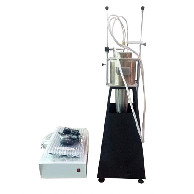
Features of the test device:
1 The test device includes a heating furnace, a test rack, an airflow hood, a thermocouple, a voltage stabilizer, a voltage regulator, a control instrument, and a computer control part;
2 Heating furnace:
2.1 The heating furnace tube is made of bauxite refractory material with a density of (2800±300) kg/m3, with a height of (150±1) mm, an inner diameter of (75±1) mm, and a wall thickness of (10±1) mm;
2.2 Heating furnace system: A heating coil is wound on the heating furnace tube according to the standard of Appendix B of GB/T5464-2010, and its exterior is covered with a heat insulation layer. The conical air flow stabilizer is fixed at the bottom of the heating furnace, and the airflow hood is fixed at the top of the heating furnace.
2.3 Heating coil: heating resistance belt, with a specification of 3mm×0.2m nickel 80% chromium 20% resistance belt;
2.4 The heating furnace tube is placed in the center of a cylindrical tube made of insulation material with a height of 150mm and a wall thickness of 10mm, and is equipped with a top plate and a bottom plate with inner concave edges to position the heating furnace tube. The annular space between the heating furnace tube and the cylindrical tube should be filled with appropriate insulation materials;
2.5 The bottom surface of the heating furnace is connected to an inverted cone air stabilizer with both ends open. It is 500mm long and evenly reduces from the top with an inner diameter of (75±1)mm to the bottom with an inner diameter of (10±0.5)mm. The air stabilizer is made of 1mm thick steel plate, and its inner surface should be smooth. The interface between the heating furnace and the air stabilizer should be tight, airtight, and smooth. The upper half of the air stabilizer is insulated with insulation materials for external heat preservation;
2.6 The combination of the heating furnace, air stabilizer and airflow hood is installed on a stable horizontal bracket. The bracket has a base and an airflow screen, which is used to reduce the airflow suction at the bottom of the stabilizer. The airflow screen is 550mm high, and the bottom of the stabilizer is 250mm higher than the bottom of the bracket.
2.7 Thermocouples are arranged in the heating furnace according to GB/T5464-2010 standard to measure the temperature in the furnace, the temperature of the furnace wall and the center temperature of the sample;
2.8 Air stabilizer: The upper part is insulated with mineral wool fiber with a thickness of 25mm and a thermal conductivity of (0.04±0.01) W/(m?K) (average temperature of +20℃). A 1mm thick stainless steel plate with a length of 500mm is used, which is uniformly reduced from the top with an inner diameter of (75±1) mm to the bottom inverted cone with an inner diameter of (10±0.5) mm.
2.9 Heating power: 1000W. In a stable state, when the voltage is about 100V, the heating coil passes a current of about 9~10A. Meet the test standard of Section 7.2.3 of GB/T5464-2010.
3 Airflow hood: Made of the same material as the air flow stabilizer, installed on the top of the heating furnace. The airflow hood is 50mm high and has an inner diameter of (75±1)mm. The inner surface of the interface with the heating furnace should be smooth. The outside of the airflow hood should be insulated with appropriate materials;
4 Heating temperature: up to 900C
5 Thermocouple:
5.1 Use a K-type thermocouple with a wire diameter of 0.3mm and an outer diameter of 1.5mm. Its hot junction is insulated and cannot be grounded. Thermocouples should meet the first-level accuracy requirements specified in GB/T16839.2, and the armor protection material should be stainless steel;
5.2 New thermocouples have been artificially aged before use to reduce their reflectivity;
5.3 The hot junction of the thermocouple in the furnace is (10±0.5) mm away from the wall of the heating furnace tube and is at the midpoint of the height of the heating furnace tube. The position of the thermocouple is calibrated by a positioning rod, and its accurate positioning is maintained by a guide rod fixed on the airflow hood (1 positioning rod).
5.4 Balance of furnace temperature: The average temperature of the furnace tested is balanced at + (750±5) ℃ for at least 10 min, and its temperature drift (linear regression) does not exceed 2 ℃ within 10 min, and the maximum deviation (linear regression) relative to the average temperature does not exceed 10 ℃ within 10 min, and the temperature is continuously recorded. From room temperature to 750°C≤1h, maintain stability.
6 Contact thermocouple: Use K-type thermocouple with a wire diameter of 0.3mm and an outer diameter of 1.5mm. Thermocouples shall meet the first-level accuracy requirements specified in GB/T16839.2. The armored protection material shall be stainless steel and artificially aged before use. They shall be welded to a copper cylinder with a diameter of (10±0.2) mm and a height of (15±0.2) mm.
7 Sample holder and insertion device
7.1 The sample holder is made of nickel/chromium or heat-resistant steel wire. A layer of heat-resistant metal wire mesh is installed at the bottom of the sample holder. The mass of the sample holder is (15±2) g;
7.2 The sample holder is suspended at the lower end of a support made of a stainless steel tube with an outer diameter of 6 mm and an inner diameter of 4 mm.
7.3 The sample holder is equipped with an insertion device, which can be smoothly lowered along the axis of the heating furnace to ensure that the sample is accurately located at the geometric center of the heating furnace during the test. The insertion device is a metal sliding rod that can slide freely in the vertical guide groove on the side of the heating furnace.
7.4 For loose filling materials, the sample holder is a cylinder. The metal mesh at the bottom of the sample rack is made of heat-resistant steel wire mesh. The top of the sample rack should be open and the mass should not exceed 30g;
8 Observation mirror: In order to facilitate the observation of continuous flames and protect the safety of operators, an observation mirror is set above the test device. The observation mirror is square with a side length of 300mm, an angle of 300 with the horizontal direction, and is placed 1m above the heating furnace.
9 Balance: The weighing accuracy is 0.01g. (Prepared by the customer)
10 Temperature recorder: It uses acquisition card, temperature sensor, temperature transmitter, and computer measurement and control. Its measurement accuracy is 0.1℃, and it can generate continuous records with an interval of 3 times/1s. The measurement error within the measurement range of +700℃ is less than ±1℃.
11 Timer: Record the test duration with an accuracy of 1s/h
12 Computer control, with reasonable structure, stable performance, easy operation and other advantages;
13 WINDOWS XP operation interface, LabVIEW style, perfect safety mechanism. During the test, the measurement results are displayed in real time, and the required temperature value and measurement time are automatically and accurately recorded, and a perfect curve is dynamically drawn. The data can be permanently saved, retrieved and printed out, and the report can be printed directly.
Packing List
| Name | quantity |
| Host | 1 set |
| Combustion furnace | 1 set |
| Test hanging basket | 1 pcs |
| Positioning rod | 1 pcs |
| Observation mirror | 1 pcs |
| Thermocouple | 3 pcs |
| Computer | 1 set |
